Lab 4 - Inverse Kinematics
Inverse Kinematics Lecture
Inverse Kinematics lecture by Jaden Clark, April 24, 2023.
Lab Instructions
Goal: 1) Learn how to compute inverse kinematics 2) Become familiar with simulation-to-real pipeline.
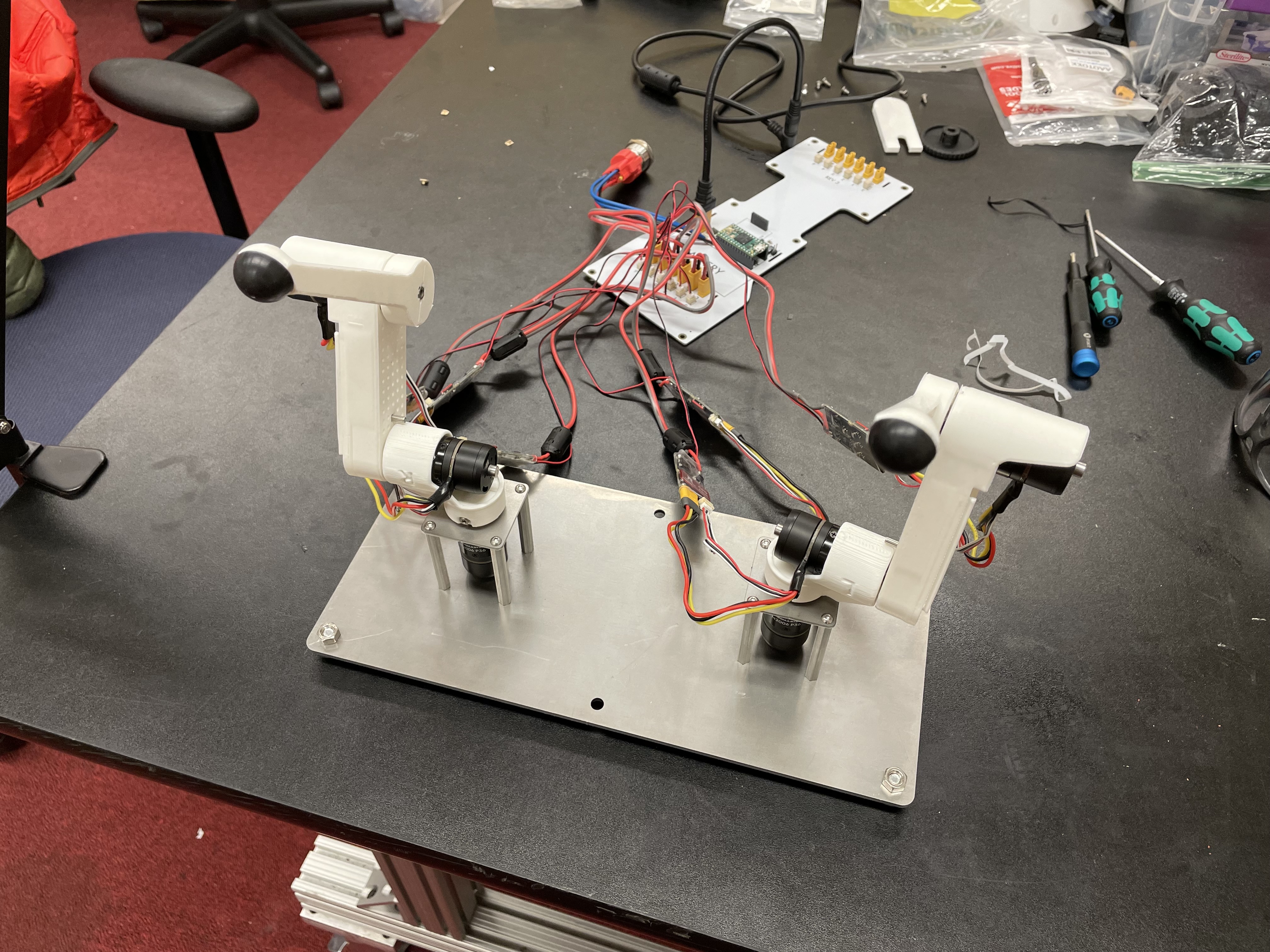
TODO: picture of sim and real robot together
Step 1. Code inverse kinematics
Implement
ik_costinreacher_kinematics.pyas the squared-norm of the error between the position returned byFK(guess)andend_effector_pos.Implement
calculate_jacobianinreacher_kinematics.pyusing the finite differencing method we covered in lecture. A good perturbation size is small, like 0.001.Implement
calculate_inverse_kinematicsinreacher_kinematics.py. Play around with different step sizes, from 1 to 100, to see what works for you.
Step 2. Test the consistency between forward kinematics and inverse kinematics
Test your code by taking some reachable (x,y,z) point in space (think hard about what’s reachable!), using your IK function to get the corresponding joint angles, then passing them to your FK function to retrieve the original (x,yz). These should match as long as the original point was reachable.
The reason we’re doing this IK -> FK consistency test and not a FK -> IK consistency test is that for any reachable point in space, the robot can flip its “elbow” joint up or down to get to that point in space, resulting in different joint angles.
Step 3. Test IK in simulation
Use the simulator to visualize your IK: Make the white sphere go to an arbitrary point in space by modifying
reacher_manual_control.py(see line 95)Use your IK code to figure out the joint angles, and then set the simulated robot’s joint commands to those angles (see line 81).
Like in lab 3, the white sphere should follow the red sphere of the robot.
Step 4. Deploy your IK to your robot
Look at the code that sets the actual robot motors, specifically line 86 and 87.
Change the joint angles sent to the hardware to those calculated by your IK.
Deploy to robot. Remember to pass the
--run_on_robotflag when you run your program.
Step 5. Make your two robot arms match each other’s end-effector positions
Calculate the cartesian end-effector position of the right arm using FK.
Use this result to calculate the cartesian position of the right arm’s end-effector relative to the base of the left arm.
Disable the right arm’s torque by de-activating the motors in the right arm. [TODO link code line number]
Deploy to robot and sanity check the reported position
Figure out what to add/subtract from the right arm’s position to get the corresponding position relative to the left arm.
Deploy to robot and sanity check that the position relative to the left arm is correct.
Use your IK to move the left arm to this position in the simulator. Check that the left arm doesn’t freak out.
Deploy to robot!
The result you should get is that the left arm and right arm are touching or very close at the end effector! You can put an object between the end-effectors and now you have a multi-robot manipulator!
Notes:
* The code is set up to control both arms, but currently we are commanding the second robot arm’s actuators to stay at zero.
* We can move the second arm by setting the values in the 3rd column (index 2) of the full_actions 2d array. See line 86 as an example.
* You might need to change the sign of some of your joint angle commands because the second arm is a right-sided leg instead of a left-sided leg.